Voltage indicating device IN 3-10R-00 UHL3 (dry contact relay)
Certificate of Conformity No. РОСС RU.ME.05.H00268.
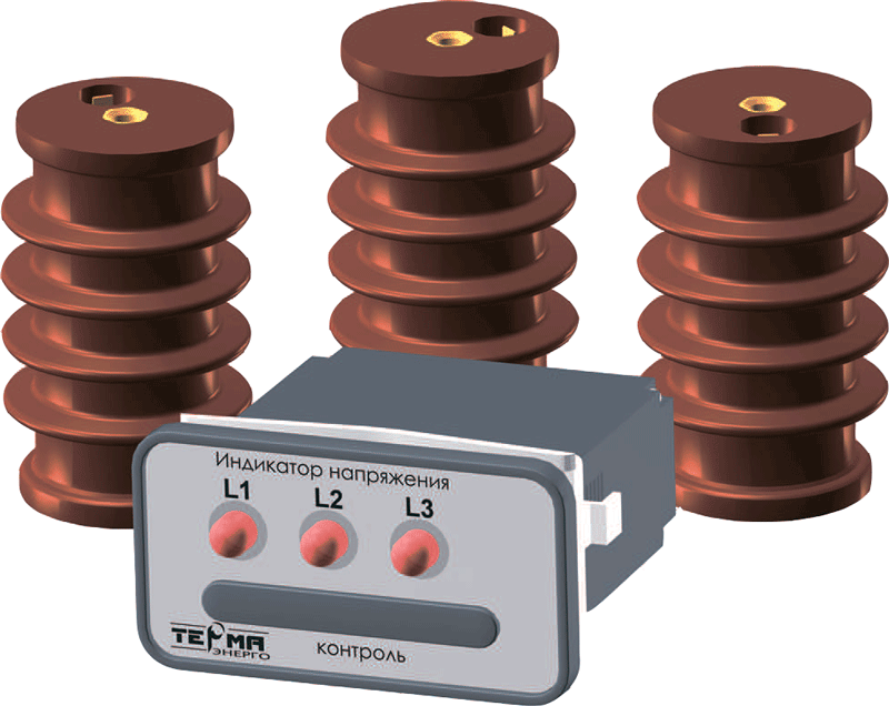
Voltage indicating device with built-in relays (stationary voltage indicator) IN 3-10R-00 UHL3 is designed to control the voltage between the busbar and the switchgear body independently in each phase in electrical installations for a nominal voltage of 6-35 kV in the frequency range of 50-60 Hz. It is used for remote and visual monitoring of operating voltage, out-of-phase mode, blocking the erroneous inclusion of grounding knives in the presence of voltage on the outgoing line, automatic input of a reserve, control of opening of contacts in the vacuum chambers of a circuit breaker, etc.
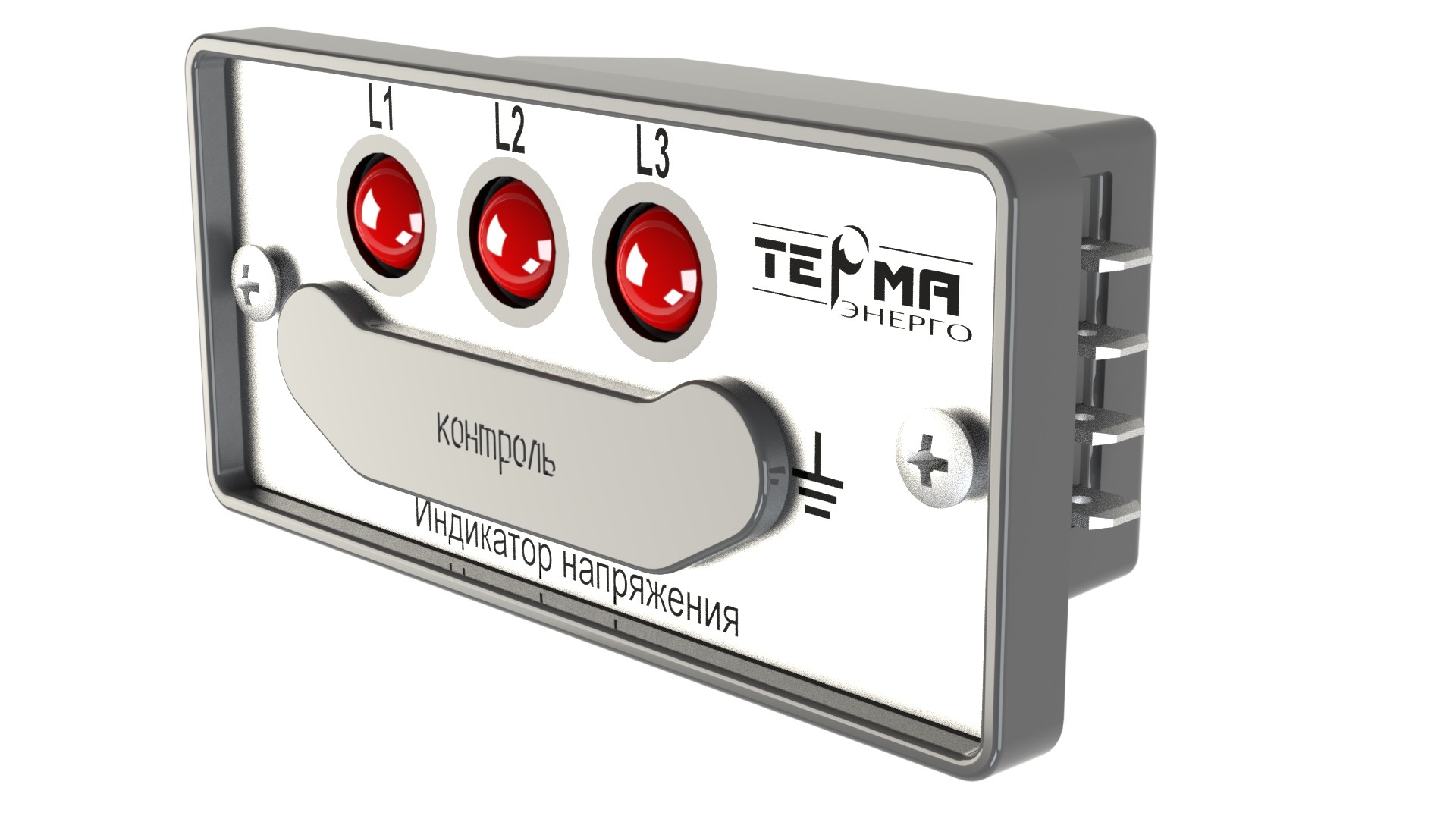
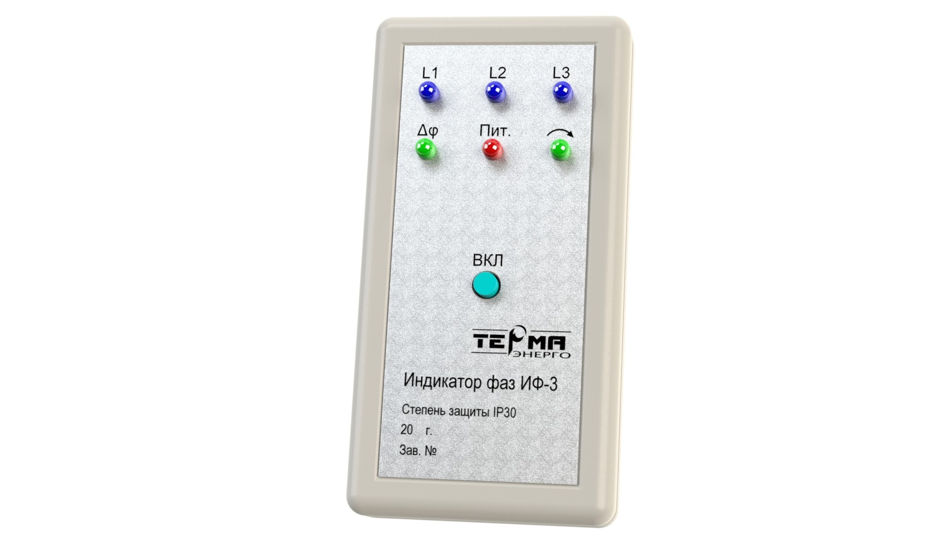
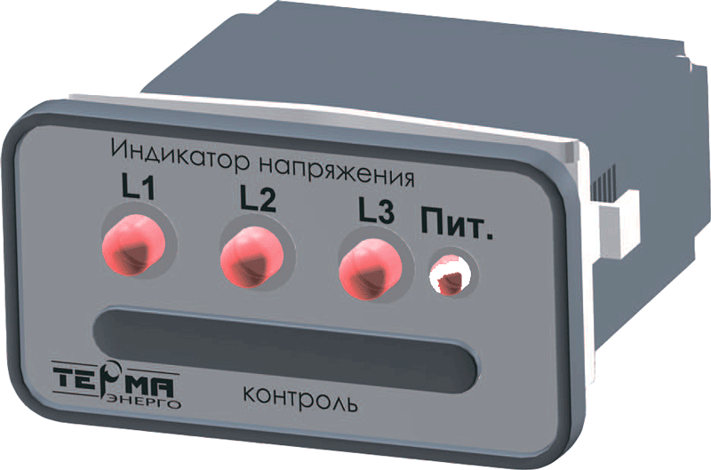
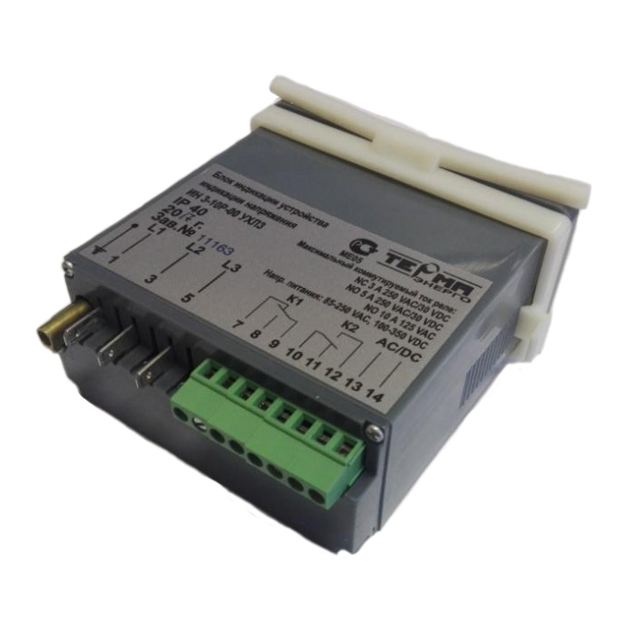
The device consists of an indication unit (with 2 dry contact relays), 3 capacitive or resistive carry electrodes and a set of connecting cables. On the front panel of the unit there are 3 red LEDs, an additional green LED, indicating the presence of auxiliary voltage in the unit, and 3 control sockets. Two relays K1 and K2 are built into the unit. Relay K1 is triggered when all three phases of the operating voltage are present. Relay K2 trips to a voltage-free state. In other cases, the relays are inactive. For operation an auxiliary supply voltage of 100-350 V DC or 85-250 V AC with a frequency of 50-400 Hz is required. Another supply voltage is acceptable in coordination with the customer. Control sockets are used to check the display unit with the testing device, as well as for “hot” phasing, and to determine the phase sequence with the IF-3 device. The voltage limiter on the control sockets is similar to the one built into the carry electrode. The marking of the output is indicated on the nameplate on the display unit.
LEDs do not require external power to indicate operating voltage. The device does not need to be turned off during high-voltage tests of industrial frequency, measuring the insulation resistance of primary and secondary circuits with a megohmmeter, and tests for lightning impulse. If during the operation of the equipment it is planned to test with a constant or rectified voltage of more than 2,5 kV, then in applications, questionnaires its necessary to indicate the configuration of the devices with capacitive carry electrodes.
In accordance with the requirements of the standard of JSC «FGC EES» STO 56947007-29.130.20.104-2011 "Technical requirements for switchgear of voltage classes 6-35 kV", carry electrodes can withstand high-voltage tests with voltage of industrial frequency 5 minutes. The output signal from any type of carry electrode 10-12 V, ~ 90 μA.
The voltage class of the device is determined by the performance of the carry electrodes. Drawings of carry electrodes, depending on overall and mounting dimensions, voltage class, mechanical bending strength, see on the “Voltage Indication Device” page.
Technical specifications:
| Frequency range of operating voltage, Hz | from 50 to 60 |
| Max voltage indication threshold value | 0,45 Unom* |
| Maximum reaction time to voltage changes, s | 1 |
| Maximum voltage on the display unit, V | 90** |
| Permissible supply voltage range, AC \ DC, V | 85-250/100-350 |
| Maximum current of relay contacts (at voltage ~ 220V), A | 3 |
| Operating temperature range of ambient air, ºС | from - 25 to + 40 |
* By agreement with the customer the threshold value for the presence of voltage can be
changed.
** Determined by the operating voltage of the arrester of the built-in protection circuits
Device equipment:
| Title | Description | Qty, pcs | Notes |
| Display Unit UN003-01-000-00 | 1 | ||
| Carry electrode | IOEL 10-1.5-165-00, IOEL 10-1.5-165-01, IOEL 10-1.5-165-02, IOEL 10-5-165-03, IOEL 10-5-165 -05, IOEL 10-5-165-07, IOEL 10-5-165-09, IOEL 10-1.5-165-50, IOEL 10-8-035-20, IOEL 20-1.5-127- 00 or IOEL 35-1.5-025-00 | 3 | |
| Connection cable | 3 | Cable length determined according to the order | |
| Testing device | TIN | 1 | Supplied on separate request |
| Phase Indicator | IF-3 | 1 | Supplied on separate request |
| Instruction manual UN003-01-000-00 | UN003-01-000-00 | 1pc.per delivered batch of devices |