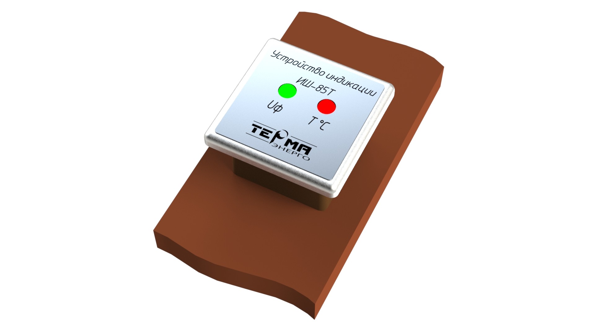
Phase indicator IF-3
The phase indicator IF-3 (hereinafter referred to as the device) is designed to determine the phases (“hot” phasing) and phase sequence in switchgear 6-35 kV and works in conjunction with voltage indicating devices of the IN 3-10 series.
Instructions of usage:
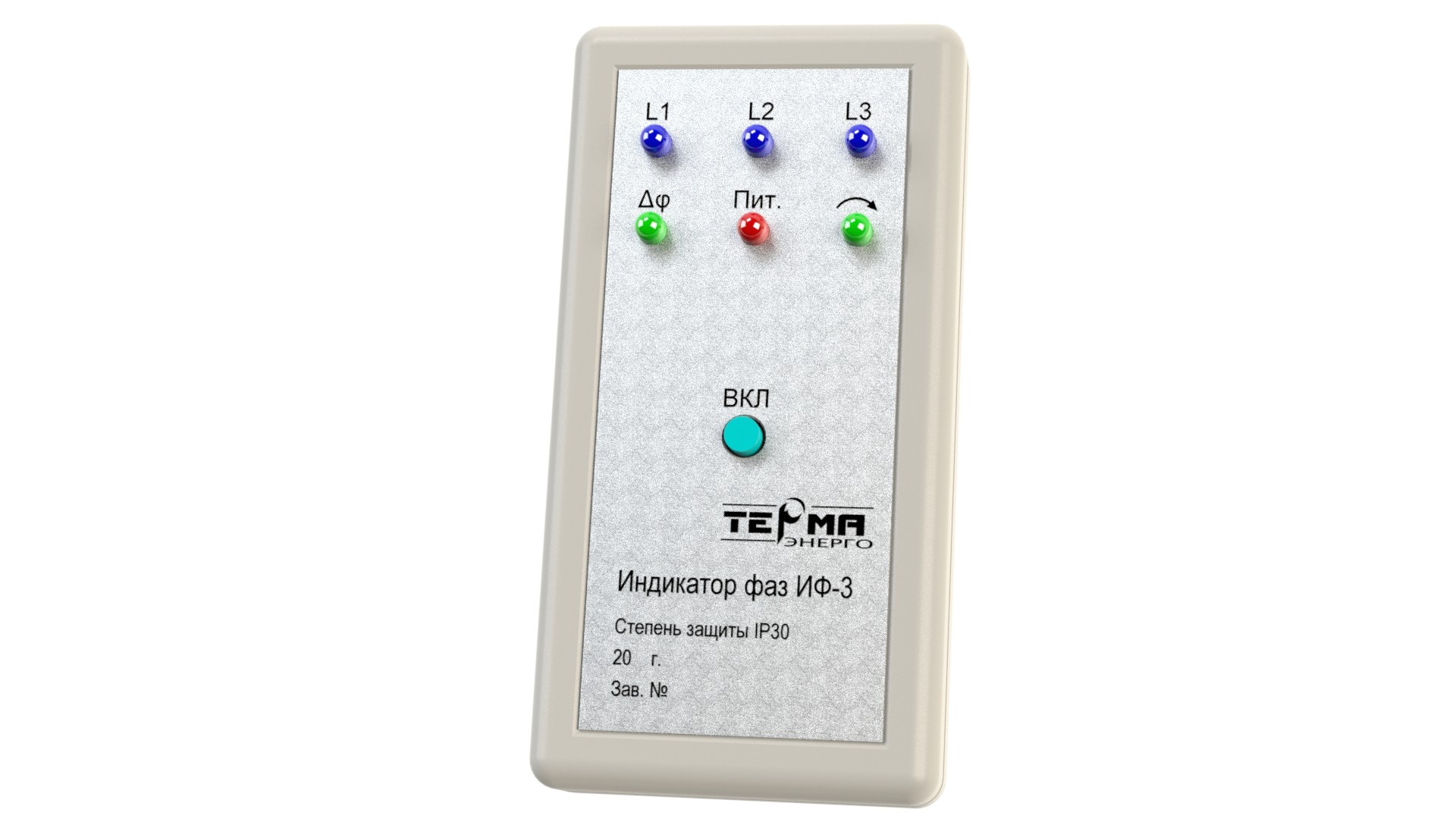
1. To check the operability of the device circuit and the battery, press the ON button. If the POWER LED lights up, the device is ready for operation.
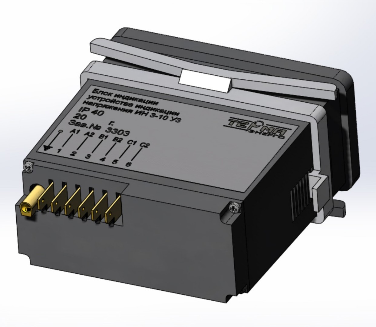
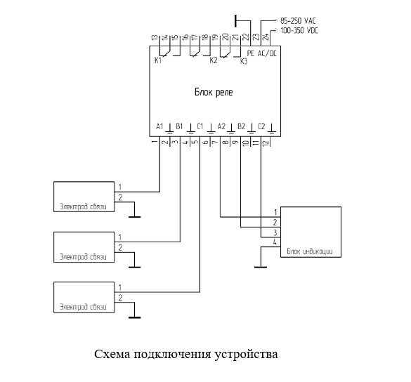
2. To check the phases matching in different switchgear cells, it is necessary to remove the protective strips on both IN 3-10 (P) -00 blocks and connect the test phases corresponding to same title, for example L1, on the IN 3-10 (P) -00 blocks with the device with cables, included in the package. Connect the first cable to the control socket L1 on the IN 3-10 (P) -00 block of the first cell and the L1 socket on the device.
Connect the second cable to the control socket L1 on the IN 3-10 (P) -00 block of the second cell and the L2 socket on the device. See fig.1 and fig.2.
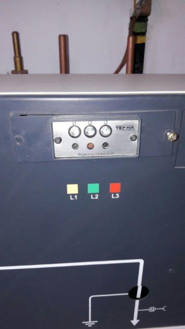
Press ON button. The L1, L2 LEDs on the device should light up, which confirms the signal arrival from IN 3-10 (P) -00 on each cable, and the LED, which means normal battery charge.
If at the same time the LED lights up, then the phases L1 in the cells match. If the LED is off, then the phases L1 in the cells are different. Similarly, phases L2, L3 in the cells are checked.
3. To determine the correct phase sequence, it is necessary to connect the control sockets of the IN 3-10 (P) -00 voltage indicator block to the device sockets L1, L2, L3 with the cables supplied with the device.
Remove the protective strip on the IN 3-10 (P) -00 unit, insert the cable with the yellow mark into the L1 sockets corresponding to same title on the voltage indicator unit and the device, insert the cable with the green mark into the L2 sockets and insert the cable with the red mark into the L3 sockets. See Fig.3 and Fig.4.
Press the ON button. The L1, L2, L3 LEDs on the device should light up, which confirms the signal arrival from IN 3-10 (P) -00 on each cable, and the LED, which means normal battery charge.
If the LED on the device lights up, the phase sequence in the cell is correct. If the LED is off, the phase sequence is incorrect.
To place an order, indicate the type of voltage indicating device of the IN 3-10 series, because the display unit WDH 97 × 97 × 49 mm and the display unit WDH 75 × 31 × 35 mm have different connectors for connecting IF-3.