Voltage indicating device IN 3-10R-03 (-05) UHL3 (dry contact relay)
Certificate of Conformity No. ROSS RU.ME.05.H00093 (TU 3414-002-73361303-2006).
The IN 3-10R-03 (-05) UHL3 devices (with 2 dry contact relays) are designed to control the presence or absence of voltage between the busbar and the switchgear body, independently in each phase in electrical installations, at a rated voltage of 6-35 kV in frequency range 50 Hz - 60 Hz according to IEC 61243-5 clause 4.9.1. They are used for remote voltage control, out-of-phase mode, blocking the erroneous inclusion of grounding knives in the presence of voltage on the outgoing line, automatic reserve input, etc.
Each device includes:
- display unit, WDH 75x31x35 mm, 1 pc.;
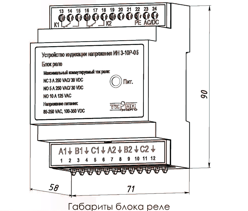
- relay block, WDH 71x58x90 mm, 1 pc.;
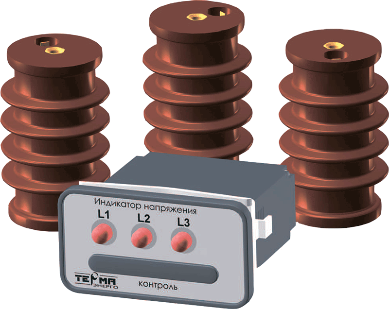
- carry electrode (sensor) resistive (for ID 3-10P-03), 3 pcs .;
- carry electrode (sensor) capacitive (for ID 3-10P-05), 3 pcs .;
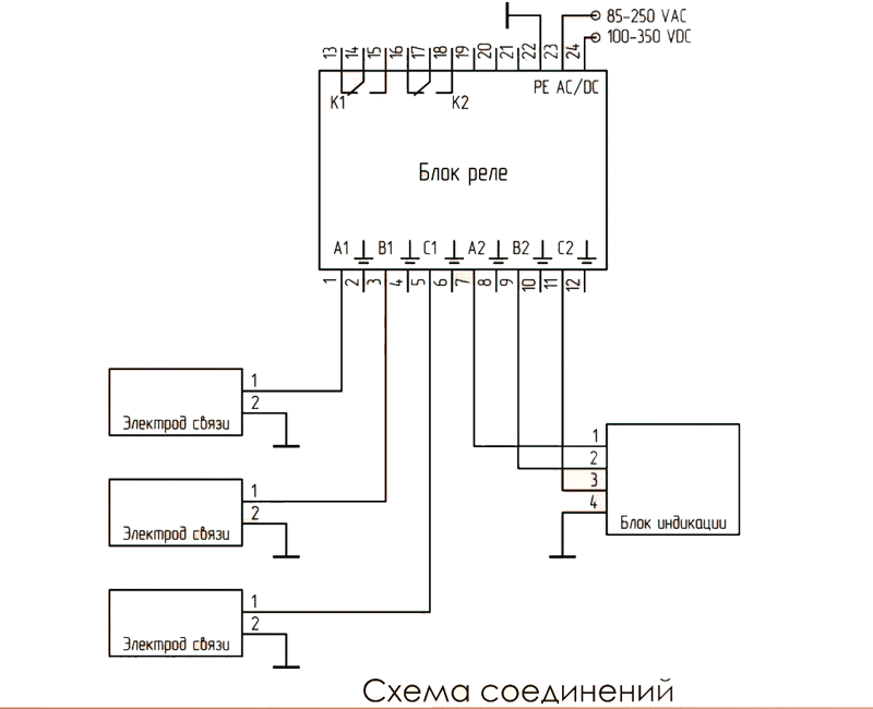
- a set of connecting cables (3 signal cables for connecting the relay unit to the power supply; 3 cables for connecting the relay unit to the display unit; 1 for grounding the display unit to the switchgear body).
The voltage class of the device is determined by the performance of the carry electrode. Drawings of various designs of carry electrodes, depending on the overall and mounting dimensions, voltage class, mechanical strength are attached on page "Voltage Indication Device". Other technical characteristics of the device depend on the design of the display unit.
Carry electrodes are made in the form of reference insulators. They are manufactured with a builtin arrester for 90 V (IN-3-10R-03) or 250 V (IN-3-10R-05) to prevent phase voltage from appearing on the carry electrode connector when the cable is disconnected or on the cable lug when disconnecting the cable from the unit indication. Also, the arrester is part of the protective circuit of the display unit. The overall and connecting dimensions of the display unit are identical to the IN 3-10-0X device block.
If during the operation of the equipment it is planned to test with a constant or rectified voltage of more than 5 kV, then we recommend to indicate in the applications and questionnaires the configuration of the devices with capacitive carry electrodes.
| Title | Value |
| Max.Threshold value of voltage indication | 0.45 Uном* |
| Maximum voltage on the indicating unit IN 3-10R-03/05, V | 90/250** |
| The voltage at the control connectors of the indicating unit IN 3-10P-05 at a nominal input voltage, V | 60-110 |
| Dimensions of the device, WDH, mm | 75/31/35 |
| Dimensions of the relay block, WDH, mm | 71/58/90 |
| Minimum indication repetition rate, Hz | 1 |
| Maximum reaction time to voltage changes, s | 1 |
| Permissible supply voltage range AC / DC, V | 85-250/100-350 |
| Maximum current of relay contacts | NC 3A 250 VAC /30 VDC; NO 5A 250 VAC / 30 VDC; NO 10 A 125 VAC |
| Protection class | IP41 |
| Operating temperature range of the ambient air for the display unit, ° С | from - 40 to + 60 |
| Operating temperature range of the ambient air for the relay unit, ° С | from - 25 to + 40 |
| Relative humidity, (max.value!),% | 98 |
* By agreement with the customer the threshold value for the presence of voltage can be
changed.
** Determined by the operating voltage of the arrester of the built-in protection circuits
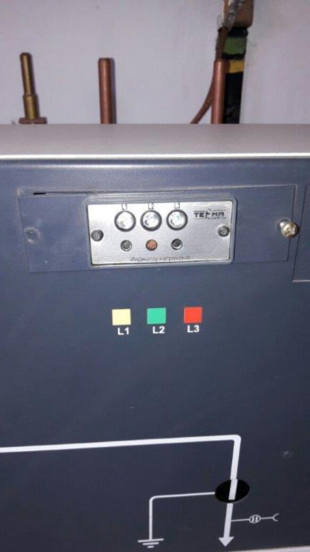
On the front panel of the display unit there are 3 LEDs and 4 control sockets: 3 phases and a “body”. When the LED is on, red indicates the presence of operating voltage. The brightness of the LED is proportional to the value of the controlled voltage.
The control sockets on the front panel of the display unit are designed to check the display unit with the testing device and determine the phase rotation, “hot” phasing with the IF-3 device. The controlled voltage enters the relay unit from the primary circuit through 3 carry electrodes, from where it is transmitted to the display unit. Two relays K1 and K2 are built into the relay block. Relay K1 is triggered when all three phases of the operating voltage are present. Relay K2 trips to a voltage-free state. In other cases, both relays are inactive. An LED is installed on the front panel of the relay unit to indicate the presence of auxiliary voltage in the unit. The output marking is applied to the block case. The relay unit is mounted on a din rail.
LEDs do not require external power source to indicate operating voltage. The device does not need to be turned off during high-voltage tests, measuring the insulation resistance of primary and secondary circuits with a megohmmeter, or lightning impulse tests.