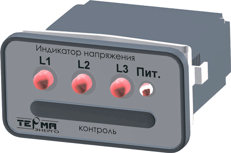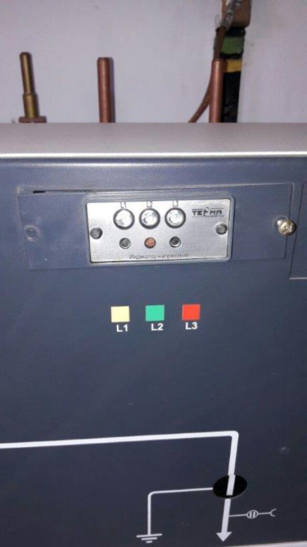
Voltage indicator IN 3-10R-10 UHL3
Voltage indicating device (stationary voltage indicator) IN 3-10R-10 UHL3 is designed for visual and remote voltage monitoring separately in each of the phases of switchgear, single-end service assembled chamber 6-35 kV, use in blocking and alarm circuits, increasing personnel safety. Specification attached in Table 1.
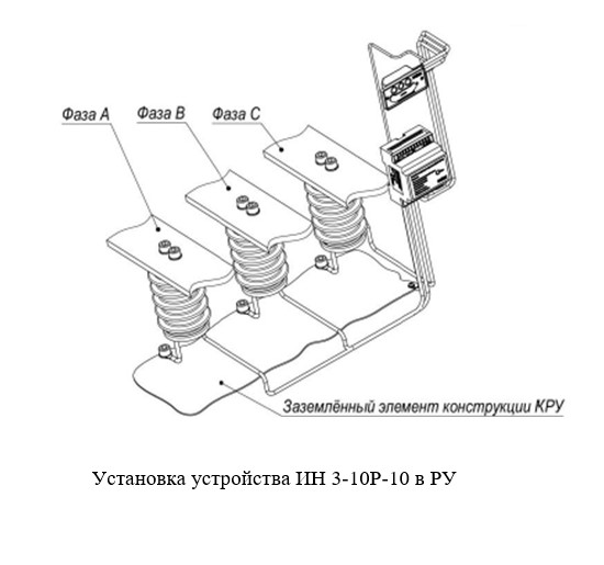
The device includes:
- display unit, 1 pc.,
- relay unit, 1 pc.,
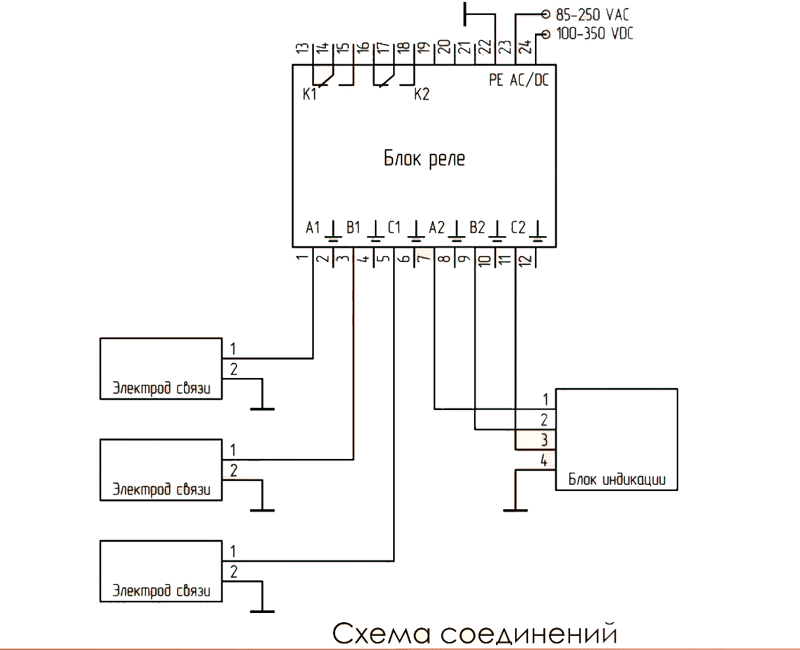
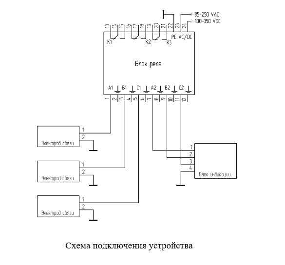
- carry electrodes, capacitive or resistive, 3 pcs.,
- connecting cables.
Table 1
| Title | Value |
| Max. threshold value of voltage indication | 0.45 Unom * |
| Max. reaction time to voltage changes, s | 1 |
| Permissible supply voltage range of the AC / DC relay block, V | 85-250/100-350 |
| Operating temperature range of ambient air, ° C | from - 25 to + 40 |
| Maximum voltage on the display unit, V | 90-250* |
| The duration of the high voltage tests, min | 5 |
| Protection class | IP40 |
* as agreed with the customer
If in devices of series IN 3-10R-00, IN 3-10R-05 there are 2 three-contact relays, where one relay is triggered for the presence of voltage in all three phases, and the second for the absence of voltage in all phases, then in IN 3-10R- 10 in the relay block there are 3 three-contact relays for monitoring the voltage separately in each phase.
Possible combinations of controlled signals are provided in Table 2. Each unit corresponds to the applied voltage, whereas 0 corresponds to its absence. Each relay is triggered for the presence of voltage in the corresponding phase. In the first, second and third columns, 1 means - the relay is active, 0 - the relay is inactive. By agreement with customer, another logic is possible.
In accordance with the standard of PJSC «Rosseti» STO 34.01-3.2-005-2016 “Prefabricated single-chamber service chambers. General technical requirements ”and the standard of JSC «FGC EES» STO 56947007-29.130.104 -2011“ Typical technical requirements for switchgear of voltage classes 6-35 kV , the device withstands high-voltage tests during 5 min.
Operational power source is not required to indicate the LEDs.
Table 2
| К1 | К2 | К3 | Operational power supply | Phase А | Phase В | Phase С |
| 0 | 0 | 0 | 0 | Any combination | ||
| 0 | 0 | 0 | 1 | 0 | 0 | 0 |
| 1 | 0 | 0 | 1 | 1 | 0 | 0 |
| 0 | 1 | 0 | 1 | 0 | 1 | 0 |
| 1 | 1 | 0 | 1 | 1 | 1 | 0 |
| 0 | 0 | 1 | 1 | 0 | 0 | 1 |
| 1 | 0 | 1 | 1 | 1 | 0 | 1 |
| 0 | 1 | 1 | 1 | 0 | 1 | 1 |
| 1 | 1 | 1 | 1 | 1 | 1 | 1 |