Voltage indicator IN 3-10-00 UHL3
Voltage indicator IN 3-10-00 UHL3.
Certificate of Conformity No. РОСС RU.ME.05.H00268.
The device is used for visual monitoring of an operating voltage presence or absence between the busbar and the switchgear body, independently in each phase in electrical installations, for a nominal voltage of 6-35 kV in the frequency range 17 Hz - 60 Hz according to IEC 61243-5, clause 4.9.1.
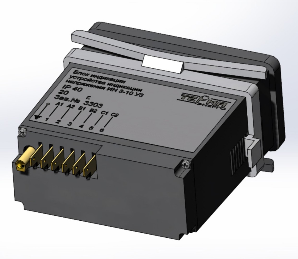
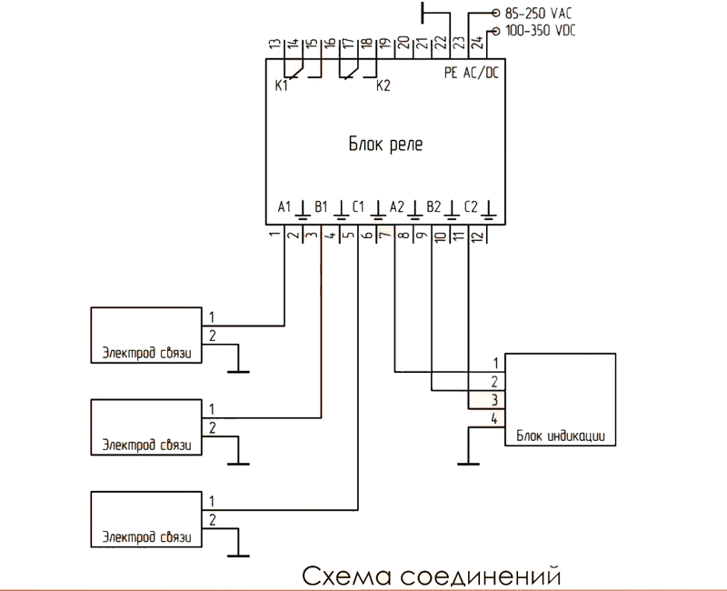
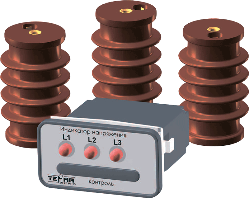
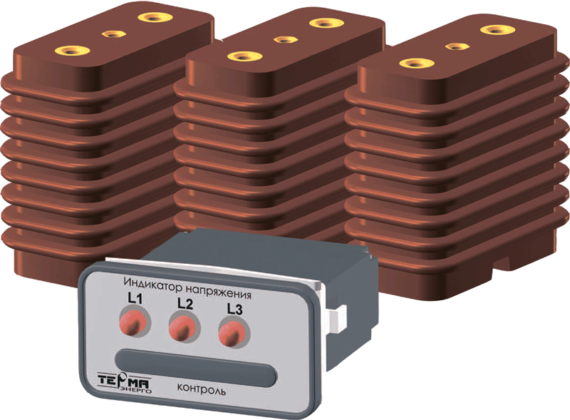
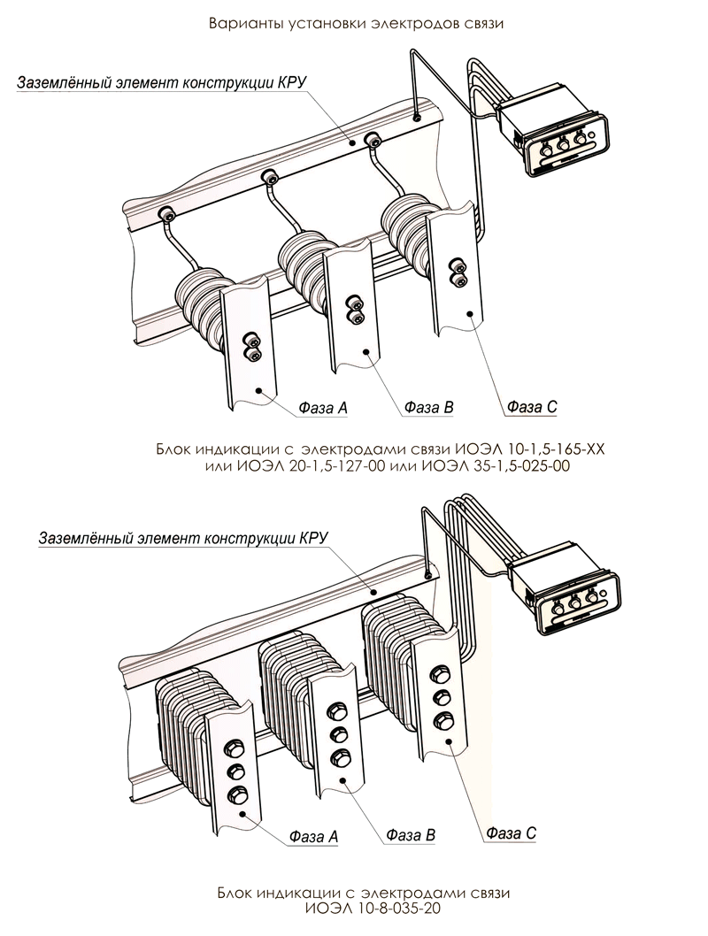
The device consists of a display unit, 3 capacitive or resistive carry electrodes and a set of connecting cables. The controlled voltage is supplied to the display unit from the primary circuit through 3 carry electrodes type IOEL 10-1.5 (5) -165-XX, IOEL 10-8-035-20, IOEL 20-1.5-127-00 or IOEL 35 -1.5-025-00 (bending strength F = l, 5 ÷ 8.0 kN). Carry electrodes are attached (with electrical contact) between the body and the corresponding phase and are connected to the display unit by connecting cables.
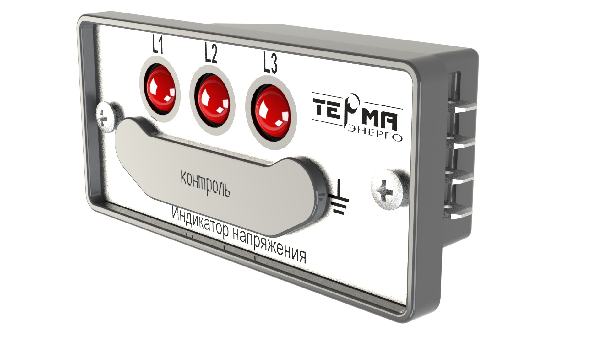
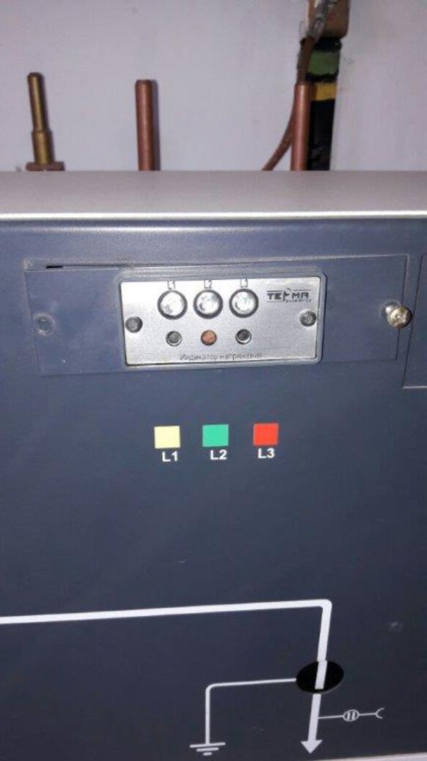
On the front panel of the display unit there are 3 red LEDs and 3 control connectors. A blinking LED indicates the presence of operating voltage. The blinking frequency of the LED is proportional to the value of the monitored voltage. Control sockets are designed to check the accuracy of the display unit using the voltage indicator testing device, which makes it possible to check the indicator in operating conditions (energized), while the entire internal circuit of the display unit and the voltage limiter built into the carry electrode are checked. Control sockets are also used for hot phasing and phase sequence determination with the IF-3. The voltage limiter on the control sockets is similar to the one built into the carry electrode.
Connecting cables are connected to carry electrodes through the FS63 flat knife switch and to the rear panel of the unit through the LSI537 knife switch. The output marking is located on the lower plane of the display unit. The protective earth contact of the display unit must be connected to the enclosure of the electrical installation cabinet.
Devices do not need to be turned off:
- during high voltage tests;
- while measuring the insulation resistance of primary circuits with a megohmmeter;
- tests for lightning impulse.
In accordance with the requirements of the standard of JSC «FGC EES», STO 56947007-29.130.20.104-2011 “Technical requirements for switchgear of voltage classes 6-35 kV”, single-end service assembled chamber and switchgear with solid organic insulation must withstand high-voltage tests during 5 minutes. Since 2014, the IN 3-10-00 U3 devices have undergone high-voltage tests for at least 5 minutes. The output signal from any version of the carry electrode (and on the contacts for phasing the display unit) is 10 ÷ 12 V, ~ 90 μA. The output marking is indicated on the nameplate on the display unit. The display does not require external power source.
The device is equipped with various designs of carry electrodes, depending on the overall and mounting dimensions, voltage class, mechanical strength, cable connection to the sensor (end or side). The voltage class of the device is determined by the performance of the carry electrode. Carry electrodes are made in the form of reference insulators. They are manufactured with a builtin 90 V arrester to prevent phase voltage from appearing on the electrode connector when the cable is disconnected or on the cable lug when disconnecting it from the display unit. Also, the arrester is part of the protective circuit of the display unit.
To place an order, in addition to the name of the device, it is necessary to indicate the preferred carry electrode design and the length of the connecting cables. If only the name of the device is indicated in the application, for example, “IN 3-10-00 UHL3”, then by default the device is equipped with resistive carry electrodes IOEL 10-1.5-165-00 series for a voltage of 6 (10) kV and cables 2,5 meters.
Carry electrode can be made in a preferred body, both in the form of post or bushing insulator.
If during the operation of the equipment it is planned to test with a constant or rectified voltage of more than 5 kV, then we recommend that you indicate in the applications and questionnaires the configuration of the devices with capacitive carry electrodes.
Carry electrode design drawings, depending on the overall and mounting dimensions, voltage class, mechanical strength (from 1.5 kN to 8 kN) are attached on page“ Voltage Indication Device”
Technical details:
| Frequency range of operating voltage, Hz | from 17 to 60 |
| Max voltage indication threshold value | 0,45 Unom* |
| Maximum voltage on the display unit, V | 90** |
| Minimum indication repetition rate, Hz | 1 |
| Maximum reaction time to voltage changes, s | 1 |
| Operating temperature range of ambient air, ºС | from - 25 to + 40 |
* By agreement with the customer the threshold value for the presence of voltage can be changed.
** Determined by the operating voltage of the arrester of the built-in protection circuits
Note:
The display unit can work with any other carry electrode, both resistive and capacitive, whose
rated current range is 50-500 μA.
Table 1:
| Designation | N, mm | Bending strength, kN | D1 | D2 | L1, mm | L2, mm | B1, mm | B2, mm |
| IOEL 10-1,5-165(065)*-00 | 120 | 1,5 | М10 | 2М10 | 16 | 16 | - | 23 |
| IOEL 10-1,5-165(065)*-01 | 124 | 1,5 | М10 | 2М10 | 16 | 16 | - | 23 |
| IOEL 10-1,5-165(065)*-02 | 130 | 1,5 | М10 | 2М10 | 16 | 16 | - | 23 |
| IOEL 10-5-165(065)*-03 | 120 | 5,0 | 2М10 | 2М10 | 16 | 16 | 23 | 23 |
| IOEL 10-5-165(065)*-05 | 130 | 5,0 | 2М10 | 2М10 | 16 | 16 | 23 | 23 |
| IOEL 10-5-165(065)*-07 | 130 | 5,0 | 2М10 | 2М8 | 16 | 16 | 23 | 18 |
| IOEL 10-5-165(065)*-09 | 130 | 5,0 | 2М10 | 2М8 | 16 | 16 | 30 | 26 |
| IOEL 10-1,5-165(065)*-50 | 130 | 1,5 | М10 | М12 | 16 | 20 | - | - |
Execution (065) differs in a groove under the terminal only for end connection of a cable (see view A2).
The position of the terminal is shown for the end connection of the cable from the indication unit. When connecting the cable laterally, bend the terminal 90 ° beforehand (see view A1).
By agreement the devices are equipped with capacitive carry electrodes.